1) Introduction: why high-end T-Glass yield problems often come back to tension stability
In high-end T-Glass weaving (high-performance glass fiber fabrics), quality issues can look unrelated on the shop floor: end breaks, fuzz, fabric waviness, uneven pick density, tight/loose edges, unstable crimp, and even downstream problems such as inconsistent resin impregnation, lamination variation, or cutting defects.
But when teams trace the root cause, many of these failures converge on one shared driver: tension fluctuation.
That is a practical reality of high-end T-Glass: it is commonly high-modulus, low-elongation, relatively brittle, and highly sensitive to surface defects. Even when the average tension is “within spec,” frequent fluctuations or short peaks can create micro-cracks or abrasion on the fiber surface. Those micro-events may not be visible immediately, but they often get amplified into irreversible defects in later processes.
The result: the yield ceiling is rarely raised by making the tension number look nice on a screen. It is raised by engineering tension stability—including ripple and peak behavior—into your system design and acceptance criteria.
> For high-end glass fiber weaving, yield is not just about the setpoint. It’s about whether the tension signal is clean, controllable, and traceable.
---
2) Why precision closed-loop tension control fits high-end T-Glass weaving
High-end T-Glass tension disturbances are usually mixed-frequency problems happening at the same time:
- Low-frequency drift: beam radius reduction, slow friction changes, gradual contamination
- Mid-frequency ripple/resonance: dancer arm natural frequency, eccentricity, drivetrain pulsation
- High-frequency spikes: shedding/beat-up impacts, momentary roller sticking, sudden path geometry changes
If you try to “force” everything with one loop (for example, one PID tuned aggressively), common outcomes include:
- It corrects low-frequency drift, but mid/high-frequency oscillation increases; or
- You reduce gain to avoid oscillation, but peaks remain, and breaks/fuzz persist.
A more implementable approach is to design the system so the problem is handled by layers, where each mechanism addresses what it is best at. In practice, that means combining:
- a suitable closed-loop tension structure
- the right sensing (and calibration/verification plan)
- an actuator/brake solution that provides controllable torque, not just “braking”
- observable data (time-synchronized) so improvement is repeatable
This is why precision closed-loop tension control is so effective in high-end T-Glass weaving: it reduces reliance on “tuning luck” and replaces it with an architecture you can validate and replicate.
---
3) Scenario mapping: identify which tension problem you actually have
Use the symptoms below to prioritize where to invest first.
Scenario A: average tension looks stable, but fabric shows periodic waviness or pick-density stripes
Most likely driver: mid-frequency disturbance (torque ripple, dancer resonance, eccentricity).
What to prioritize
- Dancer mechanism parameters (mass/damping/stroke) and control filtering (anti-resonance / notch where appropriate)
- Let-off torque smoothness and bandwidth
- Time alignment between loom cycle signals (shedding/beat-up) and tension data for correlation analysis
---
Scenario B: fuzz/dust increases and guide wear accelerates, but breaks are not necessarily high
Most likely driver: micro-slippage (stick-slip) and friction coupling.
What to prioritize
- Place measurement closer to the tension-sensitive zone to confirm whether fluctuation is speed-locked or vibration-locked
- Check wrap angles, surface treatment, and bearing drag consistency on guide rollers
- Low-speed torque stability and resolution (avoid “creeping instability” that drives micro-slip)
---
Scenario C: breaks cluster at a specific station—or only at certain beam diameter ranges (very full or nearly empty)
Most likely driver: insufficient radius compensation, inertia/friction changes, or localized resistance.
What to prioritize
- Beam radius estimation/measurement plus torque feedforward
- Peak limiting (peak clamp) or event-based suppression strategy
- Inspect that station for roller/bearing condition, alignment eccentricity, and contamination
---
4) Key selection criteria: specify sensing, actuation/braking, and mechanics as one system
4.1 Tension measurement: not “do we have a load cell?”—is the measurement point correct?
Common approaches include:
- Three-roller tension transducer (deflection roller with load sensing): good for continuous measurement and stability, but affected by wrap angle and roller friction
- Dancer arm with sensing: can also provide buffering, but must address resonance and friction dead zone
- Motor current/torque estimation: low cost but model-dependent; not recommended as the only truth source for high-end glass fiber applications
Practical specification guidance
- Put the measurement point near the process-sensitive zone (e.g., close to the shedding / on-loom tension zone). Too many intermediate rollers can reshape disturbances and hide the real cause.
- Write calibration into acceptance: linearity, multi-point verification, hysteresis, thermal drift, and dynamic response. Many “mystery defects” come from hysteresis or temperature drift rather than static accuracy.
- In fiberglass dust environments, favor contamination-resistant, maintainable modular tension roller assemblies with protective design.
---
4.2 Braking/actuation selection: you need controllable torque, not just “a brake”
In tension control, the brake/actuator exists to provide adjustable torque margin and precision. Decision-makers should focus on torque resolution, repeatability, thermal stability, and dynamic bandwidth.
Common options and where they fit:
- Servo let-off (motor + drive): highest flexibility; supports radius feedforward and inertia compensation; well-suited for high-end lines and frequent recipe changes
- Powder brake: simple architecture and fast to deploy; verify thermal fade and stability across speed ranges
- Powder clutch: used where torque coupling / tension transmission is needed; also evaluate heat behavior and stability
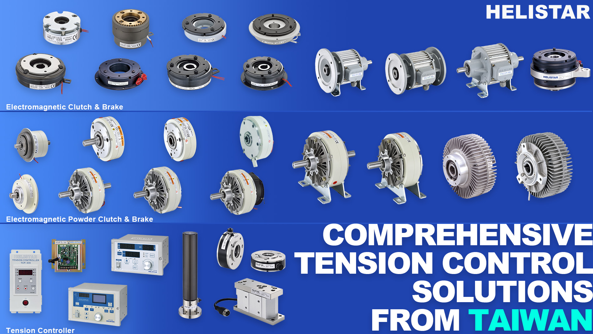
- Electromagnetic brake / electromagnetic clutch / electromagnetic clutch & brake: good for response speed and compact integration; confirm low-speed controllability and heat dissipation
Write specifications in acceptance language (not only model numbers)
- Torque resolution (Nm/LSB)
- Torque linearity / repeatability (%FS)
- Thermal stabilization time and drift (%/hr)
- Control bandwidth (Hz) and system delay (ms)
- Low-speed stability (avoid stick-slip)
---
4.3 A simple engineering relationship to validate radius compensation
A common unwinding relationship is:
T ≈ τ / R
- T = tension
- τ = let-off torque
- R = current beam radius
Plain-language meaning: as radius decreases, if torque is not reduced accordingly, tension rises.
Why it matters: your strategy must know R (measured or estimated) and apply torque feedforward, so feedback control only corrects small errors—this is how you keep tension stable.
---
5) Common mistakes, cautions, and practical notes (avoid “upgrades” that become harder to control)
1) Only specifying average tension accuracy, not fluctuation KPIs
High-end T-Glass typically cares more about RMS and peak exceedance count than a clean average value. Put fluctuation KPIs into your spec and acceptance tests.
2) Over-constraining dancer position control
Forcing the dancer to the center aggressively can inject disturbance into the tension. Use the dancer primarily for low-frequency correction and buffering, while faster loops and vibration suppression address mid/high-frequency events.
3) Ignoring dust and friction as slow, cumulative degradation
Fiberglass dust can steadily raise friction and bearing drag. A rising tension RMS is often an early warning. Without trend monitoring, the first “signal” becomes a break outbreak.
4) Choosing actuators by peak torque only—ignoring thermal stability and low-speed control
Many defects come from unstable torque (thermal drift, hysteresis, low-speed jitter), not insufficient torque capacity.
5) Recording data without time synchronization—AI cannot work
If loom cycle markers, speed, torque, and tension are not time-aligned, it becomes difficult to prove what excites what. Build observability first; then AI becomes useful.
---
6) Recommendation: make AI a yield tool through observability and acceptance—not a black box
In tension systems, AI is most practical not as a replacement for control, but as a layer that delivers three outcomes: visibility, early warning, and traceability.
6.1 Minimum signals to record (AI-ready baseline)
- Main tension (add a secondary point if needed for comparison)
- Dancer position/velocity (if a dancer is used)
- Let-off torque command and feedback (current / estimated torque)
- Line speed
- Loom cycle synchronization signal (shedding/beat-up timing marker)
- End-break / stop events with timestamps
6.2 Use interpretable indicators for dashboards and maintenance triggers
Before trying to “predict defects,” deploy indicators engineers can act on:
- Tension RMS rising: friction increase, contamination buildup, bearing degradation
- Periodic peaks locked to loom cycle: eccentricity or drivetrain pulsation
- Left-right tension distribution shifting: path resistance imbalance or alignment issue
- Peak exceedance count increasing: impacts hardening, early sticking/jamming signs
When these indicators are defined upfront and tied to acceptance criteria, your tension upgrade becomes repeatable across machines, shifts, and product styles—and AI becomes a practical yield multiplier.