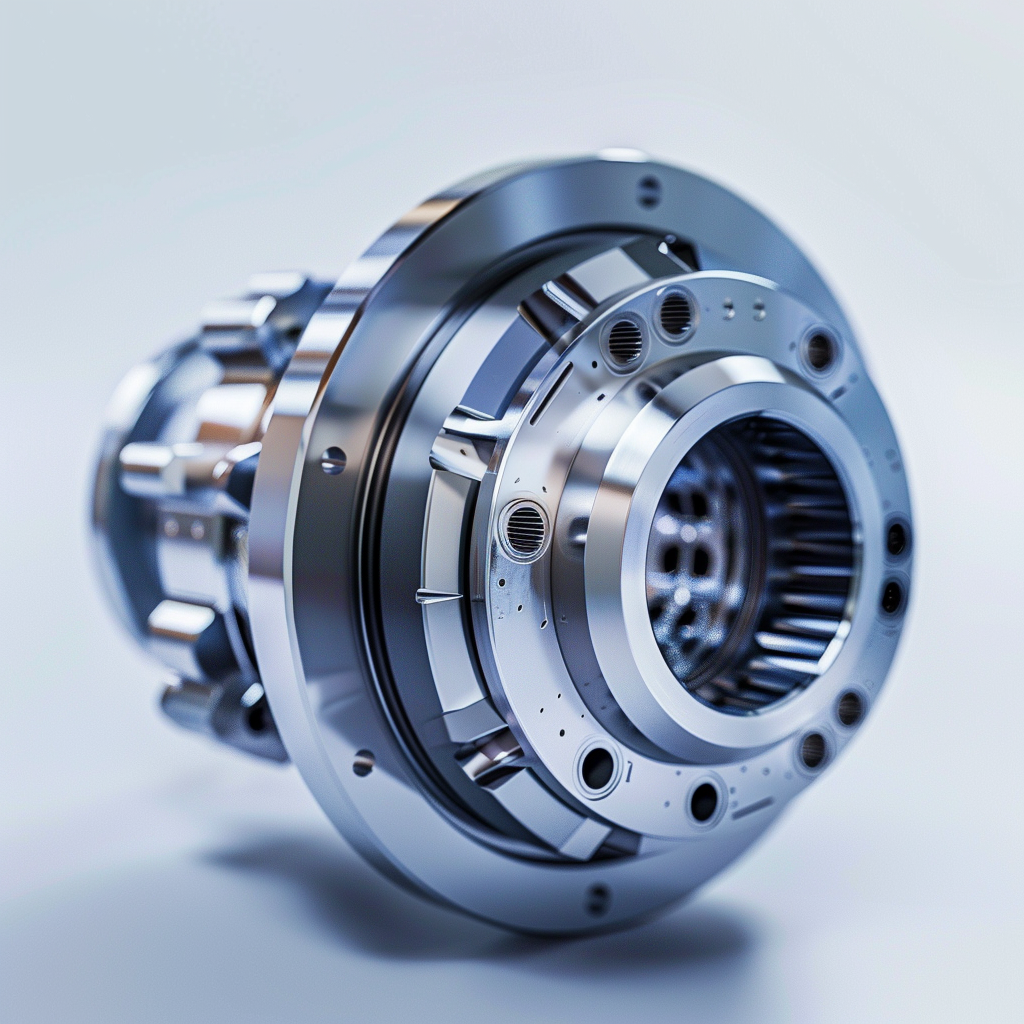
1) Starting with the Application Problem: Why Can a Protruding-Shaft Design Make Such a Difference to Tension Stability?
In continuous processes such as winding, unwinding, slitting, coating, and laminating, a magnetic powder brake is often selected on the assumption that sufficient torque is all that matters. In practice, however, many cases of tension fluctuation, abnormal bearing noise, excessive temperature rise, or prolonged changeover time are caused not by controller parameters but by an unsuitable shaft configuration or mechanical integration method.
The differences between hollow-shaft and protruding-shaft designs extend beyond their physical appearance. They directly affect:
- Installation method: direct through-shaft mounting vs integration with a coupling, pulley, or gear
- Alignment tolerance: concentricity, face runout, and periodic disturbances caused by shaft wobble
- External loads: whether belt tension or gear-meshing forces impose radial loads on the brake bearings
- Maintenance efficiency: roll-change and disassembly access, tooling requirements, and spare-parts standardization
- Tension-control quality: tension fluctuation caused by backlash, elastic deformation, inertia, and resonance coupling
This article compares HELISTAR PLB hollow-shaft and POB protruding-shaft magnetic powder brakes from an engineering-selection perspective. It also provides practical checkpoints for project implementation and acceptance testing.
2) Why Are Magnetic Powder Brakes Suitable for Tension Control?
In winding and unwinding applications, magnetic powder brakes offer several advantages:
- Controllable and continuously adjustable torque output that supports stable tension
- Generally smooth braking performance at low speeds and under slip conditions
- The ability to form a closed-loop control system when combined with a tension controller and either a tension sensor or dancer mechanism
A commonly used and intuitive relationship is:
Tension F ≈ braking torque T ÷ roll radius R, or F ≈ T / R
In practical terms, as the roll radius increases, braking torque must also increase to maintain the same tension, and vice versa.
The control system must therefore keep pace with changes in roll diameter. At the same time, the mechanical system must prevent disturbances such as shaft wobble, backlash, and radial loading from entering the tension-control loop. Otherwise, achieving stable tension becomes considerably more difficult.
3) Application Differences Between the Two Shaft Configurations: PLB Hollow Shaft vs POB Protruding Shaft
3.1 PLB Hollow Shaft — Typical Value of a Hollow Shaft Brake
Definition and integration method: The brake has a hollow bore and mounts directly onto the machine’s unwinding shaft. A clamping or locking mechanism is typically used to secure the brake and transmit torque.
Suitable machine characteristics:
- A through-shaft unwinding configuration in which the shaft passes through the machine frame
- A need to reduce axial installation length and the number of intermediate transmission components
- A need for faster changeovers and disassembly, with modular maintenance as a design objective
Engineering advantage: A shorter transmission chain introduces fewer sources of inertia and backlash, generally making it easier to achieve a simple and stable tension-control arrangement.
3.2 POB Protruding Shaft — Typical Value of a Protruding Shaft Brake
Definition and integration method: The brake has a protruding solid shaft and is commonly connected through a coupling, pulley, gear, sprocket, or another transmission component.
Suitable machine characteristics:
- The transmission architecture of an existing machine is already fixed, such as a standardized coupling interface
- On-site machining or alignment capability is limited, and a coupling is needed to accommodate part of the alignment error
- A highly interchangeable spare-parts strategy and rapid replacement of transmission components are required
Engineering advantage: It offers high integration flexibility and greater tolerance for on-site alignment conditions. However, the selection of transmission components and the management of radial loads become more critical.
4) Application Scenarios: Which Machine Configuration Do You Have?
Scenario A: Winding and Unwinding of Film, Paper, Copper Foil, or Fabric
- Prioritize PLB hollow shaft: For through-shaft unwinding, compact installation space, low-inertia design, and rapid roll changes
- Prioritize POB protruding shaft: When the existing machine already uses standardized couplings or pulleys, or when on-site shaft-end machining is restricted
Scenario B: Wire and Fiber Processing, Including Cables, Yarn, and Metal Wire
If low-speed tension consistency and reduced start-stop vibration are the main priorities:
- PLB hollow shaft generally has an advantage because fewer transmission interfaces are required
- POB protruding shaft can be paired with a low-backlash flexible coupling to reduce start-stop disturbances
Scenario C: Coating, Laminating, and Slitting with Multiple Tension Zones and Frequent Specification Changes
- For rapid modular replacement and shorter downtime, PLB hollow shaft is better suited to a through-shaft modular design
- For quick connection to an existing gearbox or belt-driven system, POB protruding shaft is easier to integrate with standard transmission components
5) Key Selection Criteria: Mechanical Design, Alignment, External Loads, and Maintenance
5.1 Engineering Selection Comparison Table
5.2 Alignment and Tolerances: Avoid a System That Fits but Does Not Run Stably
Common PLB hollow-shaft risks:
- Poor shaft-diameter tolerance, surface roughness, or radial runout may cause slipping, shaft wobble, and increased vibration
- Uneven locking or incorrect tightening torque may degrade concentricity and create abnormal bearing loads
Common POB protruding-shaft risks:
- A coupling that is too rigid converts alignment error directly into vibration and noise
- A coupling that is too flexible slows dynamic response, causing poor tension tracking and low-speed drift
- Relying on the coupling to absorb alignment error while allowing radial loads to enter the brake can shorten bearing life
5.3 Radial-Load Management: Belts and Gears Are Acceptable Only When the Load Path Is Correct
For both PLB and POB models, the primary purpose of the magnetic powder brake bearings is to support braking operation. They are not recommended for carrying high belt tension or gear-meshing loads.
Practical recommendations:
- If a pulley, gear, or sprocket must be used, provide an external bearing support to carry the radial load
- Allow the brake itself to focus on torque output, reducing the risk of damage caused by unintended structural loading
5.4 Heat Dissipation and Temperature Rise: Do Not Select by Maximum Torque Alone
In continuous-slip unwinding applications, sufficient torque does not necessarily mean the brake can operate stably over an extended period. Thermal conditions must be included in the selection process:
- Estimate continuous power dissipation using P ≈ T × ω. Higher torque and rotational speed generate heat more rapidly
- Excessive temperature rise may lead to tension drift, performance degradation, and more frequent maintenance
- If ventilation is poor or ambient temperature is high, plan forced-air cooling, heat-dissipation paths, and ventilation openings in the guard at an early stage
6) Common Mistakes and Practical Precautions
7) Quick Conclusion: How Should You Choose Between PLB Hollow Shaft and POB Protruding Shaft?
- If your priorities are a through-shaft configuration, a shorter mechanism, fewer transmission interfaces, and faster changeovers, PLB hollow shaft is generally the preferred option
- If your priorities are transmission-integration flexibility, greater tolerance for on-site conditions, and the use of a coupling to manage alignment error, POB protruding shaft is generally the preferred option
- Regardless of the selected configuration, include the following three items in the design and acceptance criteria:
- Specified alignment measurement, radial-load isolation, and adequate heat-dissipation capacity with temperature-rise validation.
When these three conditions are properly managed, the tension controller is easier to tune, and the machine becomes more stable and maintainable.