In unwind/rewind lines, slitter rewinders, wire handling, and material test stands, tension stability often determines yield and throughput. Magnetic powder brakes are widely used in constant-tension systems because they can deliver controllable braking torque while allowing slip—a practical match for continuous processes where speed and diameter change.
However, selecting a powder brake by rated torque alone commonly leads to field issues: rapid temperature rise, torque fade due to heat, low-speed tension drop, or poor matching with a tension controller/driver. This guide follows an engineering-first selection order you can apply in real projects:
1) confirm the application truly fits a powder brake,
2) verify torque and thermal load as two parallel sizing tracks, and
3) finish with control method and mechanical integration to ensure stable production operation.
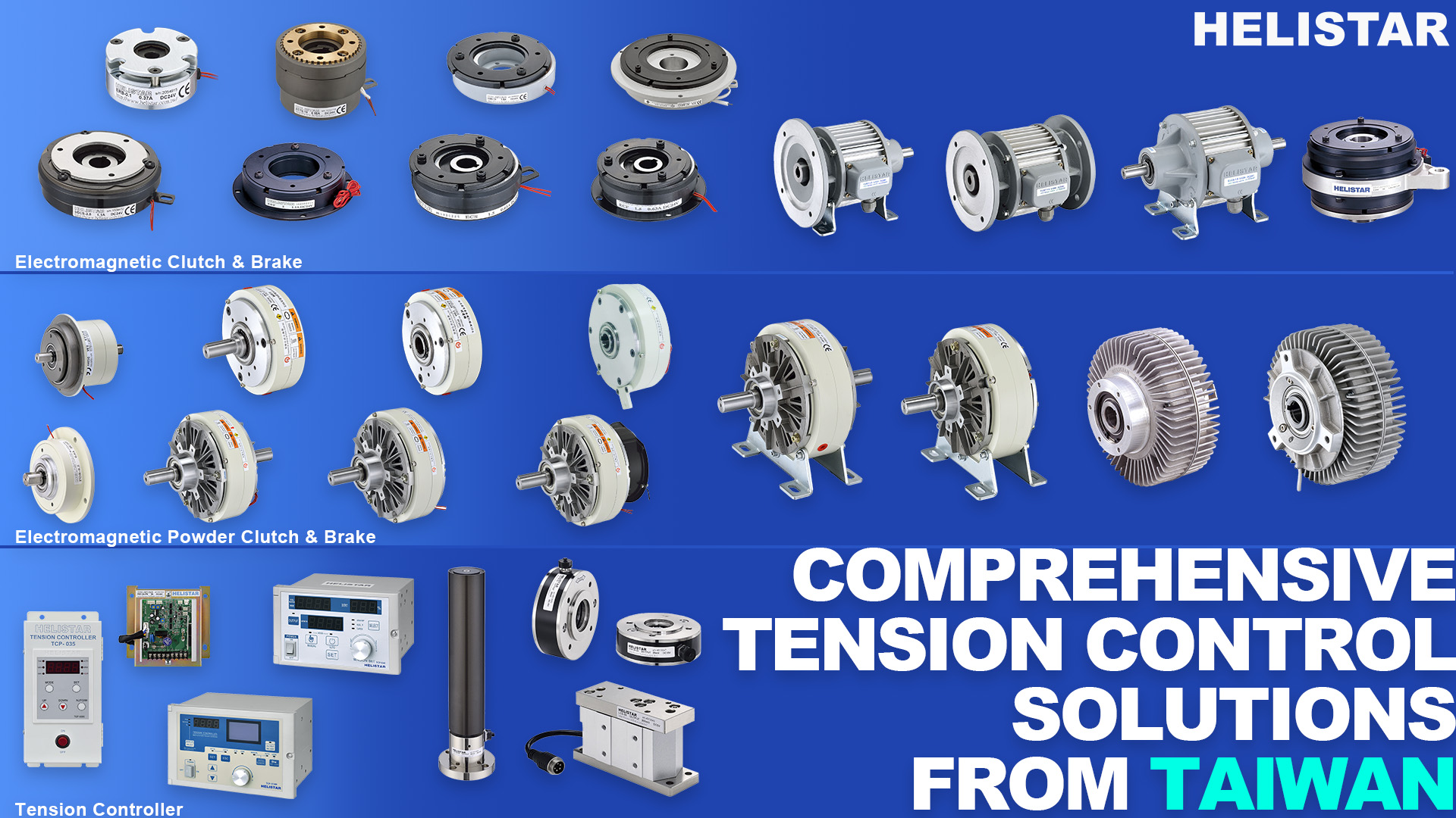
Relevant HELISTAR product families: PLB / PLBS / PFB.
---
1) First Check: Is Your Operating Condition a Good Fit for a Magnetic Powder Brake?
1.1 Why powder brakes work for tension/torque control
A magnetic powder brake contains magnetic powder between the rotor and stator. When the coil is energized, a magnetic field forms powder chains that create shear resistance—producing adjustable braking torque. In most applications, torque changes predictably with excitation current, and repeatability improves further when paired with a suitable constant-current driver and proper control tuning.
Key advantages:
- Slip is allowed: even with speed difference, the brake can output stable damping torque—ideal for unwind/rewind and slip-control systems.
- Simple control: open-loop constant-current control can work for basic cases; closed-loop constant tension is achievable with load cell feedback.
- Practical cost and integration: widely adopted for upgrading existing lines with tension control.
Trade-offs you must accept upfront:
- Mechanical energy is primarily converted into heat: thermal load (slip power) is the most underestimated limit.
- Magnetic powder is consumable: sustained high temperature or improper mechanical loading accelerates performance degradation.
1.2 Typical “good fit” vs “needs extra evaluation / alternative”
Good fit:
- Unwind / rewind tension control for film, paper, foil, laminates, wire, etc.
- Slitting / rewinding with multi-shaft tension consistency (with multi-loop tension control)
- Test stands requiring constant torque load, step/ramp load, tensile/fatigue damping load
Evaluate carefully or consider alternatives:
- Long-duration high line speed with high slip power (cooling becomes difficult; energy loss is high)
- High-efficiency or energy-regenerative requirements (regenerative servo/VFD feedback load may be a better fit)
- Very low speed with extremely low fluctuation requirements (often needs stronger closed-loop feedback + filtering, or another torque-control approach)
---
2) Why This Solution Fits Decision-Maker Priorities
Most decision makers want: stable tension, fast commissioning, controllable maintenance, and predictable cost. Powder brakes remain common in web handling because they form a relatively standardized constant-tension architecture:
- Magnetic powder brake (adjustable torque source)
- Driver/controller (typically constant-current output for torque consistency)
- Tension feedback (load cell/tension meter) + tension controller (for closed-loop when needed)
- Cooling and protection (forced air, temperature monitoring, over-temperature derating or stop logic)
So selection is not a single component comparison. It’s a system decision: torque capability + thermal management + control interface + mechanical integration. Define these clearly during selection and your chances of stable start-up rise significantly.
---
3) Scenario Mapping: What Changes Between Applications?
3.1 Unwind (Unwinder) constant tension
- Characteristic: maximum torque is often required at large roll diameter; tension must stay stable as line speed changes.
- Selection focus: peak torque and continuous cooling capability; closed-loop control (load cell + tension controller) is strongly recommended.
- Helpful features: soft-start, emergency-stop protection, web-break detection (controller/logic level).
3.2 Rewind (Winder) tension control + taper tension
- Characteristic: torque demand increases as diameter grows; some materials require taper tension (reduced tension with increasing diameter) to avoid core damage or inner-layer compression marks.
- Selection focus: torque range must cover low to mid/high tension; thermal capacity is often overlooked, especially in high-speed rewinding.
- Control note: taper tension requires diameter estimation (encoder/line-speed calculation, ultrasonic distance sensing, etc.) and an appropriate control curve.
3.3 Slitter / Rewinder multi-shaft consistency
- Characteristic: multiple shafts must hold consistent tension; low tension + high dynamics can cause low-speed hunting or shafts “pulling” each other.
- Selection focus: low-torque stability, control resolution, and mechanical concentricity; typically each shaft needs its own tension controller channel or a multi-loop architecture.
3.4 Test stand (load simulation / material testing)
- Characteristic: constant torque load, step/ramp load; may involve long-duration slip at mid to high speed.
- Selection focus: calculate thermal load first, then confirm torque; add temperature monitoring and over-temperature protection logic to prevent heat fade from biasing test results.
---
4) Key Selection Criteria (From “Works on Paper” to “Stable in Production”)
4.1 Torque sizing: back-calculate from tension and radius (most-used basic relationship)
For unwind/rewind, the simplest estimate is:
T ≈ F × R
- T: required braking torque (N·m)
- F: target tension force (N)
- R: current roll radius (m)
How to use it in practice:
- Use maximum radius (Rmax) to check the worst-case torque requirement (unwind often needs max torque at the start with large diameter).
- Convert through any belt/pulley/gear ratio to the brake shaft.
- Keep a realistic safety margin (accel/decel shocks, material sensitivity, emergency stop), and try to keep the main operating point in the mid-range of rated torque for better controllability and stability.
4.2 Thermal load and heat dissipation: the “second rating” that often decides success
The dominant risk in powder brake applications is frequently heat, not torque. In slip, energy is converted into heat inside the brake. Without adequate thermal management you may see torque drift, accelerated powder wear, and shortened life.
Selection should answer at least these three questions:
1) Is it short-time high torque (frequent start/stop) or long-time continuous slip?
2) Is the installation open air, inside a closed cabinet, or suitable for forced-air cooling?
3) Can you add an air duct, fan, or external heat-dissipation structure?
If your process is high speed + long-duration slip, decide early whether to upsize the brake, improve cooling, or adjust the control strategy to reduce slip power.
4.3 Control and driving method: think “constant current” first
A powder brake is a coil-excited device. As coil temperature rises, resistance changes. With constant-voltage driving, current can drift with temperature—and torque drifts with it.
Practical guidance:
- Prefer a constant-current driver to keep the torque-current relationship consistent.
- Match interfaces to your line standard: 0–10 V, 4–20 mA, PWM, or communications (depending on PLC/control architecture).
- For constant tension, a common structure is:
Load cell / tension meter → tension controller → constant-current driver → powder brake
4.4 Low-torque stability: don’t look only at “minimum torque”
At low current, powder brake torque can drop more easily—especially at low line speed—creating unstable tension in sensitive materials (thin films, ultra-thin foil, precision coating). Beyond choosing a suitable brake size, make sure the system design supports low-torque control:
- Use closed-loop control (load cell + tension controller) where tension tolerance is tight
- Ensure low output ripple and sufficient resolution from the driver/controller
- Apply filtering and deadband/compensation as needed to prevent hunting (constant “chasing” around the setpoint)
4.5 Mechanical integration: concentricity, bearing load path, and coupling are not optional
Many “overheats early” or “abnormal noise” cases are mechanical—not electrical. Check:
- Whether belt tension or dancer roller radial loads are carried by external support bearings, not directly by the brake.
- Shaft runout, concentricity, and installation alignment; choose a coupling with appropriate misalignment compensation.
- Sufficient cooling space (airflow direction, fan mounting, avoid heat accumulation in enclosed spaces).
4.6 Maintenance strategy: treat magnetic powder as a consumable
Common powder aging symptoms include reduced torque, increased hysteresis, and over-compensation needs. From a planning perspective, define early:
- acceptable service interval and downtime window
- whether a spare unit or quick-replacement structure is required
- whether temperature monitoring should be added for predictive maintenance (to reduce unplanned downtime)
---
5) Common Mistakes, Cautions, and Practical Notes
1) Checking rated torque only—without validating continuous thermal load
- Symptom: works initially, then torque drifts after running; fast temperature rise; accelerated powder wear.
- Fix: list continuous conditions (line speed, slip, working torque) and confirm cooling configuration or upgrade size.
2) Using constant-voltage drive and getting torque drift with temperature
- Symptom: same setting gives different tension morning vs afternoon; tension drops after heating.
- Fix: use a constant-current driver; add closed-loop load cell + tension controller if needed.
3) Eccentric mounting or applying belt tension directly to the brake
- Symptom: noise, localized heating, early bearing failure, faster powder degradation.
- Fix: correct bearing support and load path; review coupling type, alignment, and runout.
4) Demanding long-duration high-speed slip without cooling and protection
- Symptom: over-temperature stops, torque fade, inconsistent performance.
- Fix: add forced air/air ducting, temperature monitoring, and over-temperature derating/stop logic; if necessary, consider regenerative load solutions.
---
6) Recommended Selection Workflow (Easy to Align Internally and With Suppliers)
- Define the operating window: line speed range, max/min roll diameter, target tension, accel/decel and emergency stop, continuous run time.
- Estimate the torque range: use T ≈ F × R to obtain Tmax and typical working points; convert by transmission ratio.
- Confirm thermal management: is continuous slip high? can you use forced-air cooling? do you need temperature monitoring?
- Confirm control architecture: open-loop constant current is enough, or closed-loop load cell + tension controller is required? which interface (0–10 V / 4–20 mA / comms)?
- Confirm mechanics and maintenance: bearing load path, concentricity, installation space, acceptable service interval and spare strategy.
- Then map to models: match requirements to HELISTAR PLB / PLBS / PFB, including the appropriate cooling and control configuration.