1) Introduction: why winding/rewinding so often gets stuck on “tension”
In winding and rewinding lines, tension directly affects both appearance/dimensional quality and downtime/consumable cost. When tension is unstable, problems show up fast—and troubleshooting becomes difficult if you don’t have measurable trends.
Typical on-site symptoms include:
- Tension drift: the same roll becomes tight-then-loose (or the opposite), with inconsistent roll edge/roll face quality
- Wrinkles, weaving, uneven roll edges, telescoping: poor roll formation and downstream scrap
- Web breaks / edge cracking: tension spikes during acceleration/deceleration or roll changeover—especially on thin webs
- Roll-change “snap” tension: splicing/cutover or braking/drive response can’t keep up, leading to stoppage and rework
- Hard to trace root cause: no tension trend/event record, so operators rely on “feel” and repeated manual tweaks
The core challenge is simple: roll diameter keeps changing, so the same torque does not produce the same tension. That’s why “tension control for winding” is not a single component—it’s a control architecture you can verify and maintain.
One simple relationship explains the physics:
> Tension T ≈ Torque F ÷ Roll radius R
Plain meaning: as radius increases, you need more torque to hold the same tension; as radius decreases, you need less torque. If diameter estimation, torque output, or feedback measurement is unstable, tension will drift.
---
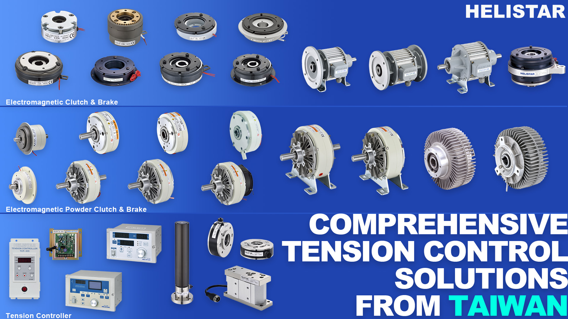
2) Why magnetic particle clutch/brake + a tension controller fits winding/rewinding
Across web-handling equipment (film, paper, nonwovens, metal foil, tape, etc.), unwind/rewind stations typically need: continuously adjustable torque, smooth output, straightforward integration, and predictable maintenance.
A common, practical configuration is:
- Unwind side: use a magnetic particle brake (PFB) to provide controllable braking torque, combined with diameter compensation and/or tension feedback to stabilize unwind tension
- Rewind side: use a magnetic particle clutch (PLB) or drive-side torque control to provide winding torque and improve roll face and roll density
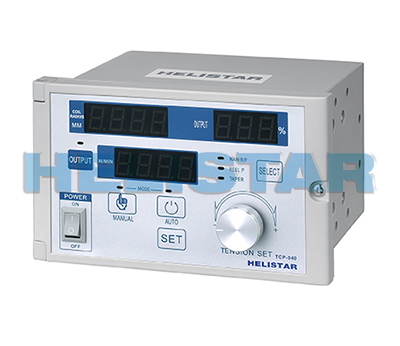
- Control core: use the TCP tension controller for setpoint management, feedback processing, and output control (supports load cell or dancer signals)
Why this approach is widely adopted in industrial winding/rewinding:
- Intuitive torque control with a wide adjustment range: supports fast commissioning and frequent product changeovers
- Controlled integration cost and complexity: compared with full servo direct-drive architectures, it delivers “stable and usable” tension control with lower system complexity
- Diameter compensation is straightforward: with diameter estimation/measurement, torque can be automatically corrected as the roll builds or unwinds
- Easy to implement segmented control: start-up, steady-state, decel/stop, and roll-change phases can use different parameters to reduce tension peaks
Important caution: for very high line speeds, ultra-low tension, or highly aggressive acceleration/deceleration, you must include thermal/energy loading in the sizing and selection. In most web lines balancing quality and cost, magnetic particle clutch/brake plus a dedicated tension controller remains a mainstream, maintainable solution.
---
3) Application differences: which tension priorities change by material/process
Different materials and process conditions require different tension priorities. Use the mappings below to decide what to strengthen first—feedback method, mechanical path, or control segmentation.
3.1 Thin films & flexible packaging (PET / BOPP / PE, etc.)
- Pain points: thin and elastic; tension fluctuation quickly causes wrinkles and edge tears
- Recommendation: prioritize load-cell closed-loop or a dancer solution; use conservative accel/decel ramps to avoid spikes
- Practical note: don’t over-filter the tension signal—too much filtering can cause loss of control during roll change and speed ramps
3.2 Copper foil / aluminum foil / battery separator film
- Pain points: high material value; tight allowable tension window; low-speed stability and spike suppression are critical
- Recommendation: high-resolution speed feedback (encoder) + closed-loop tension; implement tension upper-limit protection and torque limiting
- Practical note: pay close attention to idler drag, bearing condition, and the force path of the tension sensor—otherwise you can get “false tension” readings
3.3 Paper & nonwovens (often wide webs)
- Pain points: roll edge quality, web wandering, and tension often influence each other
- Recommendation: review tension control together with idler layout and friction path; when needed, coordinate with web guiding (EPC)
- Practical note: increasing tension to “force” tracking usually raises break/stretch risk and may worsen roll formation—solve the mechanical path and control strategy together
3.4 Tapes and tacky/adhesive materials
- Pain points: adhesive pickup and peel-force variation create tension fluctuation and surface defects
- Recommendation: use true tension feedback (e.g., load cell) and combine with anti-stick mechanisms/cleaning strategy
- Practical note: adhesive effects can cause dancer feedback misinterpretation—evaluate carefully before choosing a dancer-only approach
---
4) Key selection criteria: turn requirements into verifiable specifications
A reliable project flow is: define requirements → choose architecture → choose components. This avoids discovering “inherent limits” only after trial runs.
4.1 Define four basic inputs first
- Material data: width, thickness, elasticity/elongation behavior, allowable tension window (upper/lower limits)
- Process data: line speed range, max/min diameter, accel/decel time, whether non-stop roll change is required
- Quality targets: roll face/edge requirements, wrinkle tolerance, edge crack/break rate, appearance defect criteria
- Current pain points: which phase shows the worst issues—start-up, steady running, decel/stop, or roll change
4.2 Choosing the tension-control architecture (practical version)
- Open-loop (torque control with diameter compensation):
Simple and lower cost, but weaker disturbance rejection. Best when tension tolerance is wider and speed changes are limited.
- Semi-closed-loop (dancer):
Dancer displacement reflects tension changes and buffers disturbances, but needs mechanical space and is sensitive to friction/hysteresis.
- Closed-loop (load cell):
Directly measures tension—best for high consistency, thin webs, and foils. Success depends heavily on correct force-path installation and signal quality.
4.3 Component-level checkpoints (aligned to PLB / PFB + TCP)
- Magnetic particle brake (PFB): verify continuous torque requirement, cooling/temperature rise constraints, low-speed stability, and torque repeatability
- Magnetic particle clutch (PLB): verify rewind torque range, smooth engagement at start-up, and thermal capacity for long continuous operation
- TCP tension controller: confirm supported feedback type (load cell/dancer), sampling and filter settings, output interface, and segmented-parameter capability
- Diameter source: encoder integration, diameter sensor, or thickness-based estimation—poor diameter accuracy becomes systematic tension drift
---
5) Common mistakes, cautions, and practical notes
These are the issues most likely to cause rework and repeated tuning.
- Using higher tension to “press out wrinkles”: can look effective short-term, but increases edge cracking, elongation, and break risk—and can worsen roll edges
- Incorrect tension sensor force path: if a load cell sees side load, bearing drag, or sticking idlers, the reading drifts and becomes hard to calibrate
- Over-aggressive filtering: trends look smoother, but control becomes sluggish—roll change and accel/decel are more likely to create spikes or snap tension
- Unreliable diameter estimation: wrong thickness, unaccounted slip, or incorrect encoder sampling position can drive compensation in the wrong direction
- One parameter set for the entire process: start-up, steady-state, decel/stop, and roll change have different dynamics—use at least basic segmentation (limits and ramp-rate constraints included)
---
6) Recommendation: implement control first, then optimize
For retrofits and troubleshooting, a pragmatic rollout sequence is usually:
- Make measurement correct first: confirm stable feedback (load cell or dancer), controllable zero drift, and proper EMC/grounding
- Then complete diameter compensation: ensure diameter change does not create continuous tension drift
- Finally add segmented parameters: apply limits and ramp rates for start/stop, accel/decel, and roll change—tension peaks typically drop significantly
- Replace “feel” with data: tension trends, alarm events, and roll-change peak-to-peak values help pinpoint problems quickly and objectively