
Magnetic powder brakes — also referred to as electromagnetic powder brakes — are among the most widely used torque control components in tension control and web handling applications. Finding one that meets the nominal torque spec is the easy part. The harder part — and where most selection errors happen — is making sure the brake holds up reliably under real operating conditions: continuously changing roll diameters, sustained thermal load, low-speed demands, and clean integration with the tension control system.
A brake that checks out on paper can still produce unstable tension, overheat during extended runs, or respond sluggishly to control signals. These issues almost always trace back to selection decisions that didn’t account for the full operating envelope.
This guide walks through the four decisions that determine whether a magnetic powder brake will perform as intended — and the mistakes that most commonly lead to underperformance in the field. For background on how magnetic powder brakes work, see What Is a Magnetic Powder Brake? Working Principle Explained.
Why Getting Brake Selection Right Matters More Than You Think
In tension control applications, the brake isn’t just a passive component — it’s the primary actuator responsible for how accurately and consistently web tension is maintained across an entire production run.
An undersized brake struggles to hold torque at large roll diameters. An oversized one lacks the resolution needed for fine tension adjustment at small diameters. A brake without sufficient thermal capacity will drift as it heats up, shifting tension even when the setpoint hasn’t changed. And a brake whose excitation characteristics don’t match the tension controller will produce sluggish or oscillating response.
None of these failure modes show up on a datasheet. They surface under real production conditions — often only after the line is already commissioned and running product. The four steps below are designed to address each of these failure modes at the selection stage, before they become field problems.
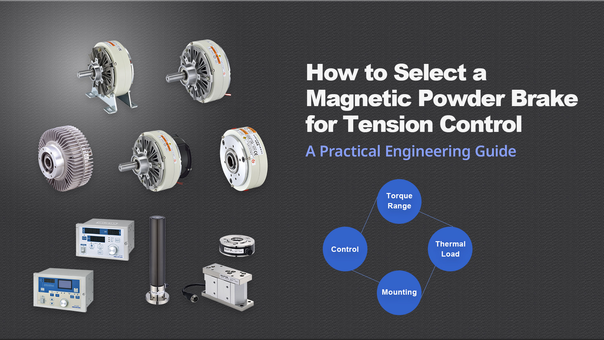
Step 1: Define Your Torque Range Across the Full Diameter Cycle
Torque is the most critical selection parameter — but it’s not a single number. The brake needs to perform correctly across the full range of roll diameters it will encounter in operation, from a full unwind roll right down to the core.
Calculate torque at minimum and maximum roll diameter
Web tension, torque, and roll radius are directly linked: torque equals tension multiplied by roll radius. As the roll unwinds and its radius decreases, the torque required to hold constant web tension decreases in proportion.
This means the brake must be able to:
• Deliver peak torque reliably at the largest roll diameter
• Maintain precise, controllable torque at the smallest roll diameter — where the absolute torque value is lowest and control resolution is most critical
A brake sized only for the midpoint of the diameter range will be running near its capacity ceiling when the roll is full, and may not have the resolution needed for accurate tension control as the roll approaches the core.
Check torque-to-current linearity at low torque levels
At small roll diameters, the brake operates at low excitation current. Confirm that the brake’s torque-to-current curve stays linear in this region. Some brakes exhibit non-linearity or a dead zone — a no-response band — at the low end of their excitation range, which makes stable tension control at small diameters difficult to achieve. Think of it as trying to steer a large vehicle through a tight space: the control inputs need to be precise, but the system isn’t responding proportionally.
Apply a torque margin
Don’t spec a brake rated exactly at your maximum required torque. A margin of 30 to 40 percent above peak demand is a reasonable starting point — it accounts for torque variation from powder wear and thermal degradation over time, and preserves headroom at the top of the control range.
Step 2: Calculate Thermal Load for Your Duty Cycle
Thermal load is the most consistently underestimated factor in magnetic powder brake selection — and the one most likely to cause in-service problems after commissioning. Getting it right at the selection stage is far less costly than retrofitting a fix after installation.
Understand how heat is generated
In tension control applications, the brake runs in continuous slip: the rotor turns while the housing stays stationary, and the magnetic powder transmits torque across this slip interface. All of the mechanical power consumed in that process converts to heat inside the brake. Unlike intermittent braking, tension control applies this thermal load continuously throughout the production run.
Calculate power dissipation
Power dissipated equals torque multiplied by slip speed in RPM (Revolutions Per Minute). In an unwind application, slip speed varies as roll diameter changes. Estimate the average power dissipation across the full diameter cycle and compare it against the brake’s rated thermal capacity. If the calculated dissipation consistently approaches the rated limit, forced cooling is required.
Choose natural or forced cooling
Natural cooling relies on conduction through the housing and convection to ambient air. It works well for moderate duty cycles, lower slip speeds, or installations where there’s adequate airflow around the brake.
Forced cooling — using forced air through the housing — is required when sustained high-slip operation generates more heat than convection can handle. Running a naturally cooled brake beyond its thermal capacity accelerates powder wear, causes torque to drift, and shortens the service life of the powder fill.
If the application calls for continuous operation at high torque and high slip speed, default to a forced cooling configuration from the start rather than treating it as an upgrade to consider later.
Step 3: Choose the Right Mounting Configuration
Magnetic powder brakes are available in several mechanical configurations, each suited to different installation geometries and drive arrangements. Choosing the wrong one can lead to alignment issues, assembly difficulties, and costly rework after the machine is built — so it’s worth locking in the installation requirements before selecting the brake, not after.
Protrudent shaft type
The rotor shaft extends from one or both ends of the housing, allowing direct coupling to the machine shaft via a flexible coupling or pulley. This is the most common configuration for retrofitting into existing drive trains or inline shaft installations.
Hollow shaft type
The brake mounts directly onto the machine shaft, which passes through the center of the unit. This eliminates the need for a coupling and reduces the overall axial footprint — making it a practical choice where axial space is tight or where maintaining shaft alignment with a coupling is difficult.
Foot-mounted type
The housing is supported by a mounting foot and can be installed directly within a machine frame, driven via pulley or chain drive. This configuration is well suited to larger drive assemblies and is available across a wide range of brake and clutch torque ratings.
Consider torque arm requirements
Hollow shaft brakes require a torque arm to prevent the housing from rotating under load. The arm must be properly sized and anchored to a rigid reaction point. If the mounting point has excessive play, housing movement under torque will indirectly introduce tension instability — assembly tolerances at this connection deserve close attention during installation.
Step 4: Match the Control Method to Your System Requirements
A magnetic powder brake or clutch is only as good as the control system driving it. Mismatches between the brake and the controller are a common source of poor tension performance — one that’s frequently misdiagnosed as a brake problem when the real issue is an incompatible control interface.
Manual control
Manual tension control adjusts DC excitation current through an operator-set dial. It’s appropriate for straightforward applications with stable tension requirements where hands-on adjustment is acceptable. It doesn’t support automatic diameter compensation or taper tension programming, so it’s generally limited to lower-demand processes.
Automatic tension control
An automatic tension controller — sometimes called a magnetic particle brake controller in application-specific contexts — takes real-time feedback from a tension sensor and continuously adjusts the brake’s excitation current to hold the tension setpoint. This eliminates the need for manual intervention and automatically compensates for tension changes caused by roll diameter variation, line speed changes, and other process disturbances.
For applications that require taper tension control, the controller calculates and applies a progressively adjusted torque setpoint as roll diameter increases — something that manual control simply can’t replicate without continuous operator involvement.
Verify electrical compatibility
The tension controller’s DC output voltage and maximum current must match the brake’s excitation requirements. Running the brake outside its rated voltage or current range shifts the torque-to-current curve, throwing off calibration and making control response unpredictable.
Confirm signal interface compatibility
If the tension controller will be integrated with a PLC or machine controller, confirm that the communication protocol, input signal range, and output signal format are compatible across every component in the control loop. Interface mismatches are easy to miss during the specification phase and time-consuming to sort out after installation.
Helistar POB Series + TCP-818D: A Validated Integration
Helistar’s POB series electromagnetic powder brakes cover torque ratings from 0.6 to 60 kgfm, available in both natural and forced cooling configurations, with protrudent shaft and foot-mounted installation options to suit different machine layouts. Every model is built for the sustained thermal and mechanical demands of continuous tension control in rewinding and web handling applications.
For closed-loop tension control, the POB series pairs directly with Helistar’s TCP-818D automatic tension controller. The TCP-818D provides DC 24V / 4A dual-channel output that drives the brake without additional power conditioning, supports taper tension programming via proximity switch or encoder input, and connects to PLCs via Modbus RTU and RS232/485 — delivering a complete, pre-validated tension control solution for rewinding, coating, laminating, and printing lines.
👉 View POB Series Powder Brake Specifications →
👉 View TCP-818D Automatic Tension Controller →
Not sure which configuration fits your application?
Share your web speed, roll diameter range, and tension requirements with Helistar’s engineering team. We’ll recommend the right POB model and cooling configuration — and confirm compatibility with your existing control system before you commit to a spec.
👉 Contact Helistar’s Engineering Team →
👉 Request POB Series Catalog →
Common Brake Selection Mistakes — And How to Avoid Them
The mistakes below account for the majority of magnetic powder brake underperformance cases seen in the field. Every one of them is preventable with the right selection process — and every one of them becomes significantly more expensive to fix after installation than before.
Application Examples: Brake Selection in Practice
The scenarios below show how the four-step selection framework plays out across different web handling applications — and how each application’s specific demands shape the final brake specification.
Common Questions About Magnetic Powder Brake Selection
Q1: How do I calculate the torque my application requires?
Start with the maximum web tension your process needs, in Newtons or kilogram-force. Multiply by the maximum roll radius at the unwind station in meters — that gives you the maximum torque the brake must deliver. Repeat at minimum roll radius to find the low-end requirement. Select a brake whose rated torque exceeds the maximum by 20 to 30 percent, and confirm that control resolution is adequate at the minimum torque level.
Q2: What’s the difference between natural and forced cooling, and how do I know which I need?
Natural cooling is sufficient when average power dissipation stays within the brake’s rated thermal capacity. Forced cooling is needed when sustained high-slip operation generates more heat than convection can remove — typically in applications running at high line speeds, high torque levels, or both for extended periods. If your application runs continuously at torque levels above 50 percent of rated capacity at significant slip speeds, start by evaluating a forced cooling configuration.
Q3: Can I use a larger brake to improve control stability?
Oversizing comes with its own drawbacks. A brake rated significantly above what the application requires will spend most of its time operating at the low end of its excitation current range — where torque-to-current linearity is least reliable and control resolution suffers. The right approach is to select a brake whose rated range covers the application’s operating demands with appropriate margin, not one that’s substantially larger than needed.
Q4: How do I confirm that my tension controller is compatible with the brake I’ve selected?
Check three things: the controller’s DC output voltage against the brake’s rated excitation voltage, the controller’s maximum output current against the brake’s rated current at full torque, and the coil resistance to confirm the controller can drive the coil across the full required range. If you’re using a Helistar POB brake with the TCP-818D controller, these parameters are pre-validated — no additional compatibility checks are needed.
Q5: How often does the brake need to be recalibrated after installation?
Calibrate after initial commissioning and again after the first full operating cycle, while the powder settles into its working distribution. After that, recalibration is typically warranted when tension accuracy starts to drift, following any service that involves the powder or coil, or as part of a scheduled preventive maintenance routine. High-duty-cycle applications will need more frequent checks than intermittent ones.